0
-
An empty cart
You have no item in your shopping cart
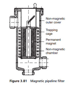
envato-wordpress-toolkit domain was triggered too early. This is usually an indicator for some code in the plugin or theme running too early. Translations should be loaded at the init action or later. Please see Debugging in WordPress for more information. (This message was added in version 6.7.0.) in /var/www/wp-includes/functions.php on line 6121g5plus-darna domain was triggered too early. This is usually an indicator for some code in the plugin or theme running too early. Translations should be loaded at the init action or later. Please see Debugging in WordPress for more information. (This message was added in version 6.7.0.) in /var/www/wp-includes/functions.php on line 6121Just like the pipeline strainers described in Section 3B, special forms of magnetic filters have been developed specifically for installation in pipelines, an easily cleaned version being illustrated in Figure 3.81. Here, the central core of the filter element
comprises a permanent magnet enclosed in a non-magnetic cover. Surrounding this cover are a number of mild steel or iron segments connected by brass strips so as to leave a small gap between each segment in which ferrous contaminant is trapped.

The purpose of the non-magnetic cover around the magnet is to ensure that it does not become contaminated with particles. Thus, the majority of the contaminants are collected between the segments, with some on the end pieces. The cages are split for ease of removal, and, once removed from the magnet assembly, are no longer magnetized, so cleaning is simple and straightforward.
Line filters of this type can be made in virtually any size. Standard productions cover flow rates from 0.5 m3/hr or less to 20 m3/hr. In the larger sizes, two or more banks of rings may be provided in the cages to increase the number of air gaps, and thus the particle retention capacity of the filter – otherwise the design follows similar lines.
As an alternative to removing the cages for cleaning, the central magnet itself may be withdrawn to de-energize the cages for flushing clean. To avoid flushing contaminant into the normal outlet, a further port is provided at the bottom of the casing for flushing direct into a separate draining bucket or receptacle.