0
-
An empty cart
You have no item in your shopping cart
envato-wordpress-toolkit domain was triggered too early. This is usually an indicator for some code in the plugin or theme running too early. Translations should be loaded at the init action or later. Please see Debugging in WordPress for more information. (This message was added in version 6.7.0.) in /var/www/wp-includes/functions.php on line 6121g5plus-darna domain was triggered too early. This is usually an indicator for some code in the plugin or theme running too early. Translations should be loaded at the init action or later. Please see Debugging in WordPress for more information. (This message was added in version 6.7.0.) in /var/www/wp-includes/functions.php on line 6121A small group of filters is classed together as variable volume devices, so called because the filtration zone containing the collected solids is compressed once filtration is complete, in order to dewater the filter cake further before discharge. The
diaphragm filter press, described in the previous chapter, fits that definition, but is more sensibly included as a variant of the horizontal filter presses, leaving two other closely related designs.
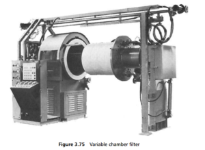
The first, known as the variable chamber (or VC) filter, was developed in the dyestuffs industry, in order to produce dyes with the maximum of mechanical dewater ing ahead of drying. It is illustrated in Figure 3.75 . It consists of two concentric hollow cylinders, the filter medium being secured around the perforated inner cylinder, while the outer cylinder is lined with a rubber diaphragm. In operation, the slurry is fed under pressure into the annulus between the filter cloth and the diaphragm. The feed pressure causes the mother liquor to pass through the medium and leave the filter.
The filtered solids are retained on the filter medium, and at an economic point, determined by volume, flow, time or pressure, the slurry feed is stopped and the cake is compressed by the diaphragm at a pressure of up to 14 bar, removing further liquor and producing a final cake that can contain less than 10% moisture.
A feature of this type of filter press is its ability to stop filtration at varying cake thicknesses. The filter is not continuous in the strict sense, since the inner cylinder

must be withdrawn in order to discharge the cake, although the turnaround period is only a matter of minutes.
The second design of variable volume pressure filter is the tube press, developed by English China Clays, for the filtration and dewatering of kaolin suspensions. It is a batch operating filter, whose principle is much the same as in the VC filter, except
that the axis of the filter unit is vertical rather than horizontal. A vertical cylinder of filter medium is enclosed by a cylindrical elastomeric sleeve, outside which is a cylindrical pressure vessel. The slurry to be filtered is introduced between the filter
element and the surrounding sleeve, at relatively low, although increasing, delivery pressures. Filtrate flows through the filter medium and the solids remain as an annular layer of cake between the medium and the diaphragm.
Once the maximum feed pressure has been reached, depending on the nature of the feed pump, then the feed system is closed and the tube press is isolated. Hydraulic fluid is now introduced between the elastomeric sleeve and the pressure vessel outside it, so as to squeeze the filter cake by means of the flexible sleeve. Squeezing pressures up to 140 bar are used, to dewater the filter cake, often to a degree of dryness where further thermal drying is unnecessary. The sleeve is then sucked off the cake by vacuum, and the inner tube is lowered free of its housing, and a pulse of compressed air cracks the cake, which falls off the candle into a receiving vessel below it.
The tube press is available in a small selection of lengths, for a constant diameter, and larger capacities are achieved by employing an array of presses side-by-side, with operations timed in sequence so that delivery of the product cake is continuous.