0
-
An empty cart
You have no item in your shopping cart
envato-wordpress-toolkit domain was triggered too early. This is usually an indicator for some code in the plugin or theme running too early. Translations should be loaded at the init action or later. Please see Debugging in WordPress for more information. (This message was added in version 6.7.0.) in /var/www/wp-includes/functions.php on line 6121g5plus-darna domain was triggered too early. This is usually an indicator for some code in the plugin or theme running too early. Translations should be loaded at the init action or later. Please see Debugging in WordPress for more information. (This message was added in version 6.7.0.) in /var/www/wp-includes/functions.php on line 6121The final group of surface filtering cartridges is made up of individual compon ents that, by themselves, could not act as a filter medium, but when assembled into a generally cylindrical shape create an external surface carrying an array of slots,
whose width defines the pore size of the filter. Probably the simplest such array is a set of circular discs stacked one above the other around a central former, which is hollow and perforated to act as filtrate off-take. Each disc has a number of slight
pimples on one side so that when they are clamped together there is a narrow circular slot at the periphery between each adjacent pair of plates, which can be made of plastic or metal. This cartridge sits in a cylindrical housing that provides the
means of holding the plates together, with flow of liquid through the stack of discs towards the filtrate collection pipe. Contaminants are removed down to a very precise dimension, set by the slot width – except, of course, that larger particles will get through if they are needle or plate shaped, so it only works well for granular particles.
The same ‘metal edge’ effect is produced by using a spring in the form of a continuous flat ribbon wound in a helical shape. With pimples on one side, and with the spring fully compressed in the cartridge housing, one long continuous slot is
formed, which has the same precise cut-point (and the same limitations about nongranular particles). Now, however, if the compression of the spring is relaxed, the adjacent turns move apart and collected dirt can easily be dislodged, from the outside of the stacked ribbon but also from between the turns.
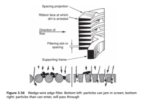
The ribbon can also be in the form of a continuous strip of wedge-wire, wound into a helix in a similar fashion, and with dimples to provide the required spacings between the turns (as in Figure 3.56 ) – but wedge-wire rings can also be formed
into a metal edge element if placed one above the other and welded to a support

structure appropriate distances apart. In either case, the broad face of the wedge is placed on the outside of the cylinder, to create the surface filtration medium.
The stack of discs is replicated in another form where the discs are circles of paper of the full diameter of the final element. Between each pair of discs is set another disc of paper of smaller diameter and high porosity through which the filtrate flows, leaving any contaminant on the outer surface of the stack or held in the annular spaces between the main discs.
The spiral effect of the ribbon is reflected in the wire wound cartridge in which a wire is wound in a close spiral around the core to form a filter medium working entirely as a surface strainer. The turns of wire are set in grooves machined on the
core, so that there is a precise slot between adjacent turns of the wire. The wire may be of metal or made from a single filament of polymer.
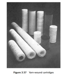
The spiral wind is also a characteristic of the yarn-wound cartridge. A multifilament yarn is wound in spiral fashion around a coarsely perforated core. Upwards of 20 layers of yarn are placed on the core, with successive turns at a pronounced
angle to the circumference of the forming cylinder, and with this angle reversed in successive layers. The resulting effect is to create a mass of diamond-shaped apertures, and a very tortuous path for the liquid in its flow through the wrapped yarn
(Figure 3.57). This gives a very effective depth filter, with filtration not only in the apertures between the turns of the yarn, but between the fibres in the yarn as well. The yarn may be of natural or synthetic fibre.
The specific advantage offered by the yarn-wound cartridge is that of compactness – a high filtration area to cartridge volume ratio: a 250mm long by

A quite different filtration medium is created in another stacked disc filter. Here the discs are quite flat and are held together by compressing springs. However, in the flat surfaces of each disc are machined a set of grooves with a triangular crosssection. These grooves run from the centre of the disc to its periphery, but at an angle to the radius, and this angle is in the opposite direction on the two sides of the disc. Thus when the discs are clamped together a large number of groove intersections are created. The irregular path for the fluid along a groove, then through an intersection, with a choice there of which grooves to follow, makes for many sharp changes of direction for the suspended particles, with a high probability that solid particles will be trapped at the intersections. The number of intersections is determined by the groove/radius angle. When the stack is full, the pressure holding the discs together is relaxed, allowing them to be spun by the incoming jets of liquid, and so release the trapped solids. This type of filter is used for the straining of process and working fluids.
Ask for more information, please click here.