0
-
An empty cart
You have no item in your shopping cart
envato-wordpress-toolkit domain was triggered too early. This is usually an indicator for some code in the plugin or theme running too early. Translations should be loaded at the init action or later. Please see Debugging in WordPress for more information. (This message was added in version 6.7.0.) in /var/www/wp-includes/functions.php on line 6121g5plus-darna domain was triggered too early. This is usually an indicator for some code in the plugin or theme running too early. Translations should be loaded at the init action or later. Please see Debugging in WordPress for more information. (This message was added in version 6.7.0.) in /var/www/wp-includes/functions.php on line 6121Even in its most highly automated form the filter press is a relatively simple machine, comprising a series of flat filter chambers mounted vertically one beside the other, between two end plates, one fixed and the other movable horizontally,
so as to close the plates together. In the earliest form of filter press, the chamber was created by means of two components: a basically flat plate carrying the filter medium and a spacer frame in the form of a wall around the outside of the chamber, which created the space in which the separated solids could collect.
The surface of the flush plate was machined or moulded to provide flow channels for filtrate liquid to run across this surface to the filtrate discharge point(s). A sheet of appropriate filter medium would be placed across the face of the plate, to be supported by the edges of the plate and by the shoulders of the flow channels in it. The frame would then be clamped to the plate, with its sheet of medium, by an identical plate on the other side of the frame. The plates would be double sided, so that each plate could be part of two successive chambers.
This pattern of plate/medium-frame-medium/plate/medium-frame would be repeated along the filter until sufficient filtration area had been built into the system, and the filter would then be closed by bringing up the queen (movable end) plate, carrying a sheet of medium, to be clamped against the last frame of the series. This whole array would then be pressed hard up against the fixed king plate at the other end of the filter (also carrying a sheet of filter medium), to create the whole filter press, formally termed a plate and frame (filter) press.
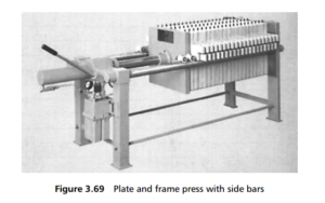
The plates and frames were suspended by lugs fitted integrally as part of the top of each, from overhead suspension beams, running usually on roller bearings. Alternatively, the plates and frames had lugs protruding from their sides that ran on support bars along each side of the filter press (as in Figure 3.69 ). The plates and frames were closed up together, along the support bars, between the two end plates, and held close enough together to provide seals between adjacent components of the filter press. The closure of the plates was effected by a hydraulic ram, or mechanically, or by electrically powered screws. Once the filtration cycle was complete, the clamping pressure was relaxed and the plates and frames were moved back along the support beams, to allow the filter cake to be removed from each chamber – which would normally have been done one chamber at a time.
As each plate had a sheet of suitable filter medium fitted over its face, so the spacer frame had filter media on either side of it. The plates, frames and media

sheets all had sets of matching holes in them so that when the filter was closed, flow channels were created along the length of the filter (provided that the sheet of filter medium was accurately placed on the frame). The slurry to be filtered was
then fed to the filter through appropriate ports in the fixed king plate, and flowed along corresponding channels through every plate in the array. As it passed each spacer frame it entered the chamber and filled it with slurry. The fluid pressure in
the slurry caused filtrate to flow through the filter medium into the drainage channels on the face of the plate, then along these channels to the filtrate exit port, which was usually at the bottom of the plate. The solids left behind accumulated
in the cake space and gradually filled it, starting at the surface of the filter medium, and growing in thickness towards the centre of the chamber.
When the cake space was nearly full, the delivery pressure of the slurry would start to rise (or the filtrate rate to fall), giving the signal to stop filtration. If the cake was to be washed, then wash liquor could be introduced from the same channel as
the feed (simple washing), and could then be discharged with the filtrate or separately. Alternatively, special wash ports may have been used, to give flow across the thickness of the cake (through washing).
With the cake washed and adequately drained (using compressed air as necessary to remove the last traces of liquid), the filter press would be opened from the queen plate inwards, and the cake in each compartment be discharged into a collection
trough or screw conveyor below the filter. Once every cake was discharged, and the filter media washed, then the filter would be closed and the cycle repeated.
Plate and frame presses (and the other types of filter press described below) are made with every conceivable combination of inlet and outlet position. The filters are often used with precoat, when bottom inlet and top outlet positions are considered best.